11 min to read
DIY Torque
Most digital torque adapters are built around 1/2 inch square drive. This project is for smaller 1/4 inch hex bit work, where the usual automotive adapters are too bulky.
The goal is a compact torque checker/adapter for repeatable workshop use. It is not a certified torque instrument.
Design targets:
- low end target of 3 Nm or lower
- 20 Nm upper working range
- 1/4 inch hex bit holder or extension format
- USB-C powered prototype with a small 1S LiPo option
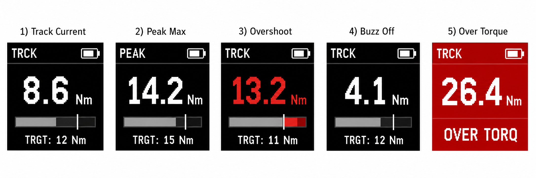
- live torque, peak torque, and tare
Selected hardware:
- LILYGO T-QT Pro, 4 MB flash + 2 MB PSRAM version
- NAU7802 breakout, a strain gauge amplifier and 24-bit ADC
- four separate BF350-0.1AA or equivalent strain gauges
- 250 mAh 1S LiPo battery, if the enclosure needs the smaller cell
System overview
The measuring chain is:
torque element -> strain gauges -> Wheatstone bridge -> NAU7802 -> T-QT Pro display
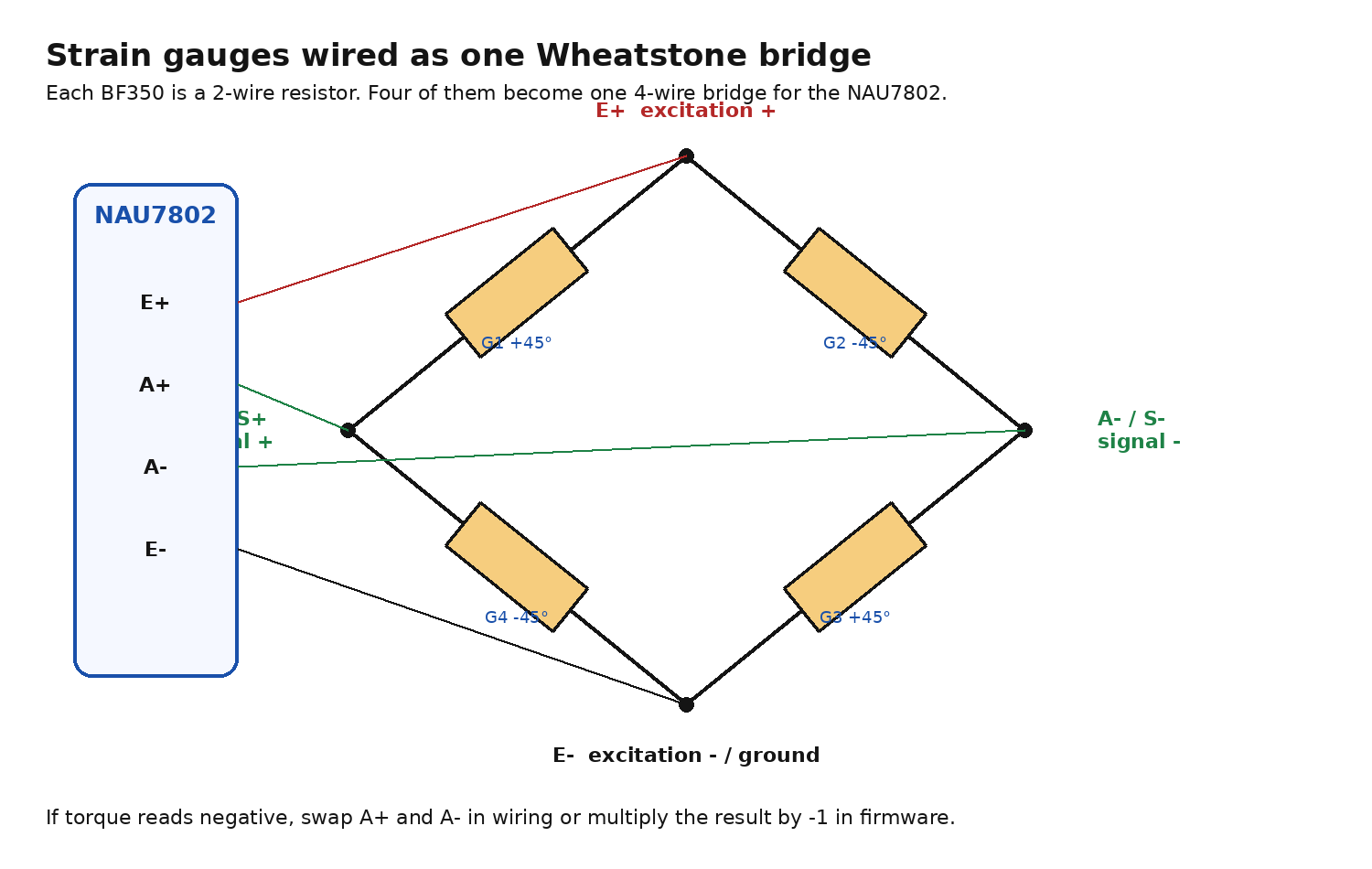
The steel bit holder or extension twists slightly under load. Strain gauges bonded to the steel change resistance as the shaft twists. Four gauges form a Wheatstone bridge. The NAU7802 powers that bridge, amplifies the tiny differential signal, and sends ADC readings to the T-QT Pro over I2C.
How torque becomes a number
Torque is force applied at a distance from a pivot:
\[T = FL\]For a hanging mass on a calibration arm:
\[T = mgL,\qquad g \approx 9.81 \ \text{m/s}^2\]Example:
\[T = (5 \ \text{kg})(9.81 \ \text{m/s}^2)(0.50 \ \text{m}) \approx 24.5 \ \text{Nm}\]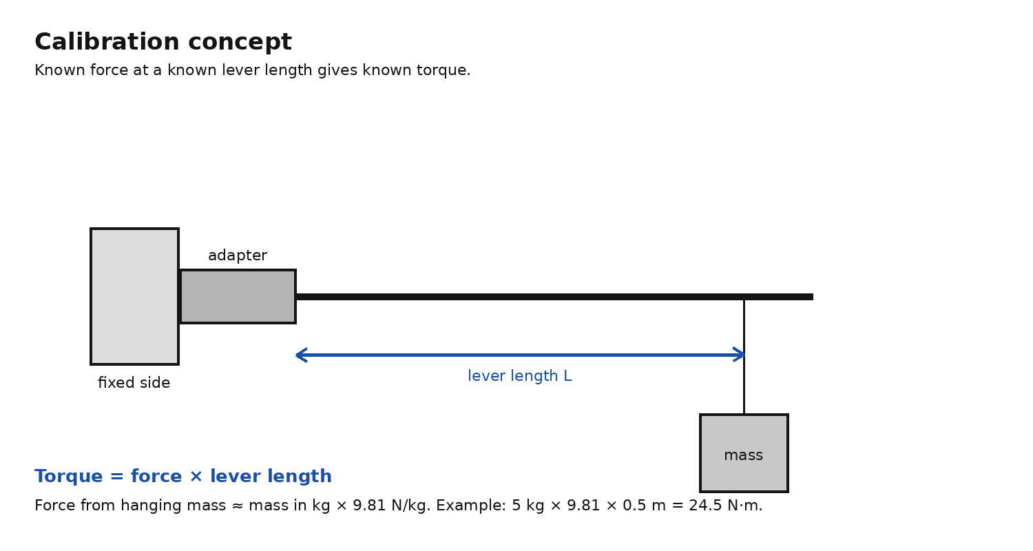
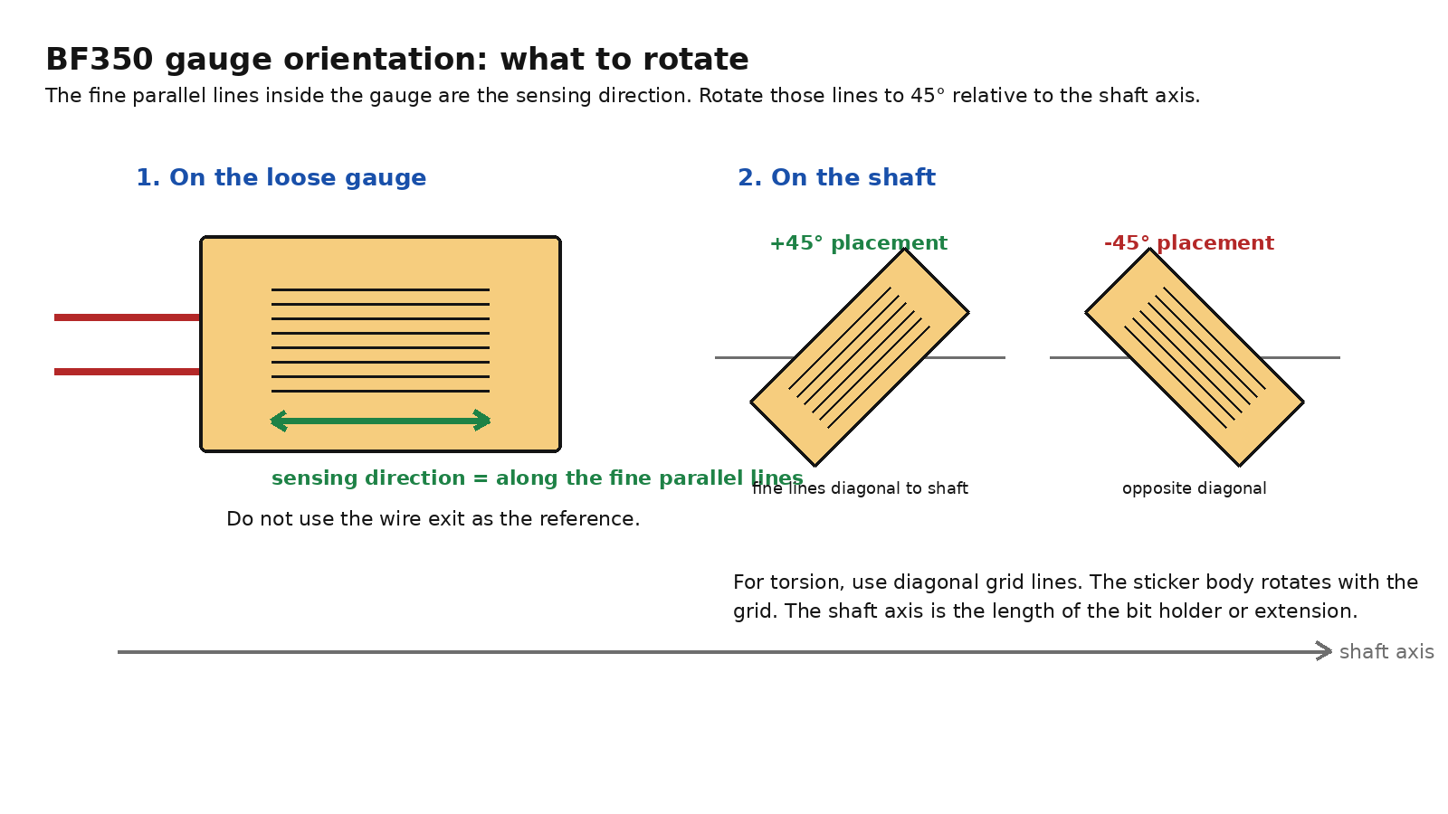
A round shaft under torsion has its strongest surface strain roughly 45 degrees from the shaft axis. That is why the gauges are placed at alternating +45 and -45 degree angles. The exact placement is covered in the mechanical build section.
The bridge output is close to zero with no torque applied. After calibration, firmware subtracts the zero reading and divides by a scale factor to estimate torque.
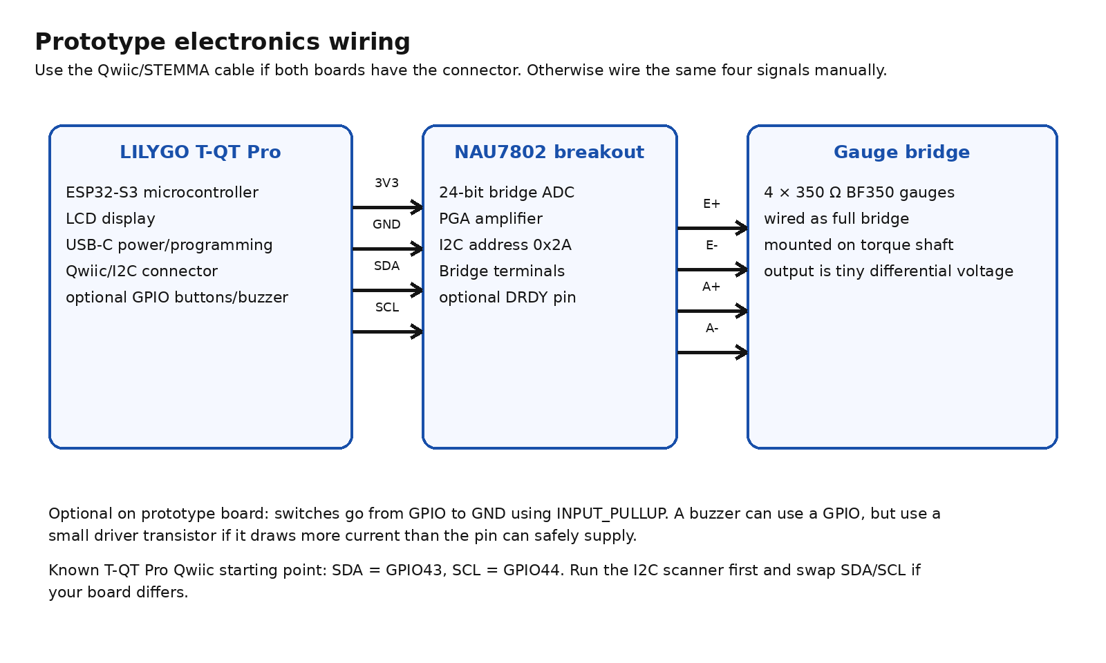
Parts and wiring
T-QT Pro
The T-QT Pro is the first controller choice because it already has the MCU, display, USB-C power/programming, and a Qwiic/STEMMA-style I2C connector. The selected variant is the 4 MB flash + 2 MB PSRAM version.
Community notes for this board point to GPIO43 as SDA and GPIO44 as SCL. The I2C scanner is the sanity check before committing to that pinout.
NAU7802
The NAU7802 is the strain gauge front end. It has a 24-bit ADC, a programmable gain amplifier, bridge excitation pins, and a fixed I2C address of 0x2A.
Typical breakout wiring:
| T-QT Pro side | NAU7802 side | Purpose |
|---|---|---|
| 3V3 | VIN | Power |
| GND | GND | Common ground |
| GPIO43 or SDA | SDA | I2C data |
| GPIO44 or SCL | SCL | I2C clock |
| not required first | DRDY | Optional data-ready signal |
Bridge wiring:
| NAU7802 terminal | Bridge node |
|---|---|
| E+ | Excitation positive |
| E- | Excitation negative |
| A+ | Signal positive |
| A- | Signal negative |
Controls and pin plan
The enclosure uses four external buttons. The onboard buttons are avoided because their placement does not work well for this layout.
| Button | Short press | Double tap | 3 s hold |
|---|---|---|---|
| Power / Clear | Clear | - | On / Off |
| Mode | Track / Peak | - | Backlight |
| Up | +1 Nm | +5 Nm | - |
| Down | -1 Nm | -5 Nm | - |
Pin plan:
| Function | T-QT Pro pin | Connection | Notes |
|---|---|---|---|
| NAU7802 SDA | IO43 | Qwiic/STEMMA SDA | Reserve for amplifier I2C |
| NAU7802 SCL | IO44 | Qwiic/STEMMA SCL | Reserve for amplifier I2C |
| Button: Power / Clear | IO16 | Button to GND | Internal pullup |
| Button: Mode | IO17 | Button to GND | Internal pullup |
| Button: Up | IO18 | Button to GND | Internal pullup |
| Button: Down | IO48 | Button to GND | Internal pullup |
| Buzzer module signal | IO35 | Module I/O pin | Active buzzer module |
| Buzzer VCC | 3V3 | Module VCC | 3.3 V active buzzer |
| Buzzer GND | GND | Module GND | Common ground |
| Battery | JST battery pads/connector | 1S LiPo | T-QT Pro supports battery charge/discharge |
| Avoided | IO0, IO47 | Onboard buttons | Bad placement for this enclosure |
| Reserved | IO1, IO2, IO3, IO5, IO6, IO10 | LCD pins | Display |
Battery and runtime
The enclosure may force the battery down to about 250 mAh. That is still plausible for short workshop sessions if the firmware has auto shutoff and the display is not left bright.
Assume usable capacity is roughly:
250 mAh x 0.8 = 200 mAh usable
Runtime estimate:
| Active current | Runtime | 30 min sessions |
|---|---|---|
| 40 mA optimized | ~5.0 h | ~10 sessions |
| 55 mA good | ~3.6 h | ~7 sessions |
| 70 mA likely | ~2.9 h | ~5 to 6 sessions |
| 90 mA high | ~2.2 h | ~4 sessions |
| 100 mA bad | ~2.0 h | ~4 sessions |
Component drain estimate:
| Component | Current estimate | Notes |
|---|---|---|
| ESP32-S3 / T-QT Pro board | ~20 to 50 mA | Biggest variable |
| LCD/backlight | ~10 to 25 mA | Dim aggressively |
| 350 ohm strain bridge | ~9.4 mA | Continuous while measuring |
| NAU7802 | ~2 mA | Small load |
| Buzzer | ~0 idle, ~10 to 30 mA active | Average is low unless constantly beeping |
| Board overhead | ~2 to 10 mA | Regulator, charger, LEDs, leakage |
Expected active draw:
normal: ~60 to 90 mA
optimized: ~40 to 55 mA
For 30 minute sessions with auto shutoff, a 250 mAh cell should be workable. Plan around 4 to 6 real sessions per charge. More is possible if the screen is dimmed and the bridge/display are shut down when idle; less is likely if the display is bright and the ESP32 is left running fast.
Mechanical build
Shaft choice
The first spring element is a high-quality 1/4 inch hex bit holder.
Rationale:
- the selected gauge fits on the existing hex flats
- no grinding is required
- the signal should be strong at low torque
- the format stays compact and matches the project goal
A 1/4 inch hex shank has:
Across flats: 6.35 mm
Individual face width: ~3.67 mm
The working scope is:
Target low end: 3 Nm or lower
Upper working range: 20 Nm
A 1/4 inch steel shank should produce a readable strain signal. The practical limit is whether the shaft stays elastic through the working range. Heat treatment, grooves, detent cuts, transitions, and socket cavities all matter.
Good candidates:
- straight 1/4 inch hex section
- high-quality or impact-rated bit holder
- minimal grooves
- no detent hole in the gauge area
- no socket cavity under the gauge area
- longest clean hex section available
Poor candidates:
- deep retention grooves near the measurement area
- thin neck-downs unless they are intentionally used as the torsion section
- short stubby adapters with complex geometry
- gauge placement over transitions or cuts
A failed zero-return test at 20 Nm points to a stronger torsion section with 1/4 inch hex interfaces.
Gauge selection and prep
The bridge uses four separate two-wire gauges:
\[R_{gauge} = 350 \ \Omega\]| Item | Decision |
|---|---|
| Model direction | BF350-0.1AA or equivalent |
| Approx. substrate size | ~1.4 x 2.22 mm |
| Gauge factor | ~2.0 |
| Why | Small enough to fit on a 1/4 inch hex flat at 45 degrees |
A prebuilt four-wire load cell is the wrong final sensor. It already has its own mechanical element; this project needs gauges bonded directly to the bit holder or extension.
The gauges need bare, clean metal under the active area. Plating only comes off where the gauges sit. The goal is strain transfer, not cosmetics.
| Item | Decision |
|---|---|
| First prototype adhesive | Thin CA glue |
| Better adhesive later | M-Bond 200 |
| Rejected adhesives | Gel CA, thick epoxy, 5-minute epoxy, silicone, rubberized adhesive |
| Reason | The bond layer needs to be thin and hard so shaft strain transfers cleanly into the gauge |
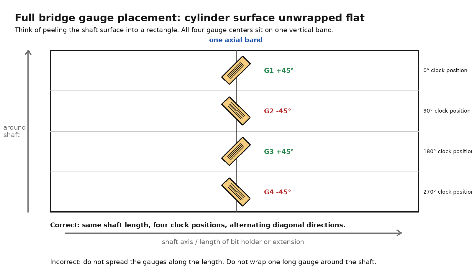
Sensor placement
On the BF350, the fine parallel lines inside the active area are the sensing direction.
All four gauge centers sit on one narrow band around the shaft.
Shaft end view:
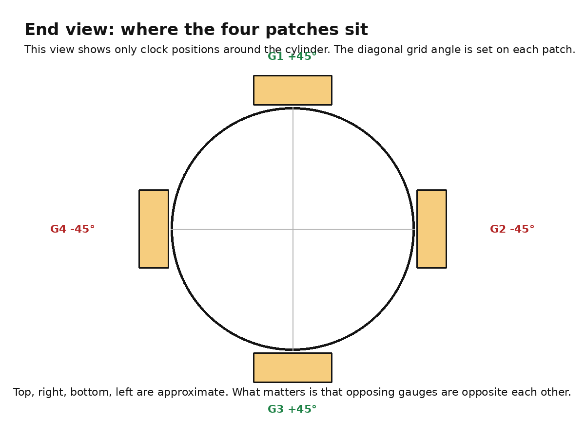
Placement rule:
| Gauge | Clock position around shaft | Fine-line direction |
|---|---|---|
| G1 | 0 degrees, top | +45 degrees |
| G2 | 90 degrees, right | -45 degrees |
| G3 | 180 degrees, bottom | +45 degrees |
| G4 | 270 degrees, left | -45 degrees |
A negative reading under tightening torque is only a sign convention problem. A+ and A- can be swapped, or the sign can be inverted in firmware.
Validation and calibration
Software setup
Arduino IDE is enough for the first hardware proof. The needed pieces are:
| Software/library | Purpose |
|---|---|
| Arduino IDE | Compile and upload sketches |
| ESP32 board package | Adds ESP32-S3 support |
| Adafruit NAU7802 library | Reads the NAU7802 |
| TFT_eSPI library | Drives the T-QT Pro display |
| LILYGO T-QT examples/config | Reference display setup |
The display can be brought up from the LILYGO examples. The NAU7802 should appear in an I2C scan at 0x2A.
Electrical test
The first electrical test uses a dummy Wheatstone bridge instead of bonded gauges:
\[R = 350 \ \Omega\]Passing signs:
T-QT Pro powers up
I2C scanner finds 0x2A
NAU7802 raw reading is stable enough to tare
Display updates
Bonded gauge validation
The bonded-gauge check is the first test of the actual sensing element:
- Four gauges bonded to one shaft band.
- Full bridge wired into E+, E-, A+, and A-.
- No-load tare captured.
- Raw readings move consistently under torque.
- Opposite sign under reverse torque.
Calibration
Calibration can come from a torque wrench or a lever-and-weight setup. A single linear scale factor is enough for the first prototype.
Calibration points:
\[T = [0,\ 1,\ 3,\ 5,\ 10,\ 15,\ 20] \ \text{Nm}\]The useful data is the raw reading while loading and unloading. Poor zero return points to mechanical hysteresis, a weak gauge bond, wire strain, or overload.
The shaft decision comes from zero return:
tare
apply torque
release
check zero
Torque progression:
3 Nm
5 Nm
10 Nm
15 Nm
20 Nm
A shaft that does not return to zero after release is not suitable at that torque.
Scale factor:
\[\text{countsPerNm} = \frac{\text{raw}_{known} - \text{raw}_{zero}}{T_{known}}\]Firmware conversion:
\[T = \frac{\text{raw} - \text{zeroOffset}}{\text{countsPerNm}}\]Remaining validation
The remaining work is mostly validation, not feature design:
- display bring-up on the T-QT Pro
- NAU7802 visible at
0x2A - stable dummy-bridge readings
- clean hex holder selected
- bonded bridge with repeatable raw response
- calibration from the low-end target through 20 Nm
- zero return checked at each torque step
- buttons, buzzer, and battery added after the sensor readings are repeatable
Open decisions
| Decision | Current leaning |
|---|---|
| Exact bit holder | High-quality or impact-rated holder with the cleanest hex section |
| Final adhesive | Thin CA first, M-Bond 200 later if the prototype proves the geometry |
| Final package | Decide after sensor geometry is proven |
Sources
- LILYGO T-QT GitHub repository: https://github.com/Xinyuan-LilyGO/T-QT
- LILYGO T-QT Pro product page: https://lilygo.cc/en-us/products/t-qt-pro
- T-QT Pro I2C pin discussion, GPIO43 SDA and GPIO44 SCL: https://github.com/Xinyuan-LilyGO/T-QT/issues/26
- T-QT Pro Qwiic silkscreen/pinout discussion: https://github.com/Xinyuan-LilyGO/T-QT/issues/17
- Nuvoton NAU7802 datasheet Rev 2.6: https://www.nuvoton.com/export/resource-files/en-us–DS_NAU7802_DataSheet_EN_Rev2.6.pdf
- Adafruit NAU7802 guide: https://cdn-learn.adafruit.com/downloads/pdf/adafruit-nau7802-24-bit-adc-stemma-qt-qwiic.pdf
- SparkFun Qwiic Scale NAU7802 Arduino library: https://github.com/sparkfun/SparkFun_Qwiic_Scale_NAU7802_Arduino_Library