22 min to read
From Zero To Mini Homelab
Planning
Introduction
Project Goals
This home lab project is designed to be a practical, efficient, and educational** setup for learning, experimenting, and self-hosting services. The key goals include:
- Networking Knowledge: Understanding how networking components interact, including VLANs, firewalls, routing, and security.
- Virtualization & Containers: Setting up and managing virtual machines (VMs) and containerized workloads using platforms like Proxmox, Docker, or Portainer.
- Low Cost & Maintenance: Achieving a reliable setup with minimal energy consumption, noise, and upkeep.
- Practical & Usable: The final solution must be functional for daily use, not just an experimental project.
- Self-Hosting for Independence: Reducing reliance on cloud services by hosting key services like Home Assistant, backup solutions, and media streaming in-house.
Why a Home Lab?
A home lab provides an isolated environment to experiment with enterprise-grade technologies at home.
Requirements
This project must balance several factors to be functional, reliable, and maintainable:
- Physical Constraints
- Must fit within the DeskPi T0 which is a 4U, 10-inch mini rack.
- Components should be efficiently arranged for airflow and accessibility.
- Power Efficiency
- Preference for low-power devices such as devices which use embedded CPUs such as the Intel N100.
- Passive cooling where possible to reduce noise and energy waste.
- Network Performance
- 2.5GbE minimum with potential expansion to 10GbE.
- Consideration of VLAN segmentation for improved security and traffic management.
- Aesthetics & Clean Design
- A well-organized setup with minimal cable clutter
- Efficient power delivery to avoid multiple bulky adapters.
- Scalability & Extensibility
- Ability to add more storage, network interfaces, or compute power over time.
- Modular approach to hardware selection.
Another factor is cost.
Software & Services
Rationalizing Bare Metal vs Virtualized Deployments
While it is certainly possible to run everything in a virtualized environment, certain services are better suited for bare metal deployment.
-
Bare Metal: Services that require low latency, direct hardware access, or high availability are best run on dedicated hardware. This includes networking components like routers, NAS systems, and DNS servers that must always be available.
-
Virtualized: Services that benefit from scalability, snapshots, portability, and resource sharing are ideal for virtualization. These include applications like media servers, password managers, and smart home hubs that can be easily moved or backed up.
Another consideration is security and isolation. Services run on bare metal are not at risk of virtualization vulnerabilities. A compromised hypervisor could potentially expose VMs.
Software & Services
| Service Type | Software Options | Deployment Method |
|---|---|---|
| DNS Sinkhole | Pi-hole, AdGuard, Technitium DNS | Bare Metal |
| Router | pfSense, OpnSense, RouterOS | Bare Metal |
| NAS | TrueNAS (x86), OMV (ARM) | Bare Metal |
| Media Server | Jellyfin | Virtualized |
| Cloud Storage | Nextcloud, Seafile, FileRun | Virtualized |
| Mobile Backup | TBD | Virtualized |
| Password Manager | Bitwarden (Vaultwarden) | Virtualized |
| Smart Home | Home Assistant, Frigate | Virtualized |
| VPN | WireGuard | Virtualized |
Form Factor
Mini Rack T0
- 1U spacing is
- 44.45mm (1.75 inch) high
- 220mm (8.75 inch) horizontal clearance
- Rack depth is 200mm (7.87 inch) deep, this is not strict, since you can have devices hanging off the back
- Total height of 4U of space is available
Other Options
- https://www.walmart.ca/en/ip/Lanview-10-6U-Rack-Wallmount-Cabinet/27ED1727QWW0?from=/search
- https://gaiacom.ie/products/digitus-dn-10-06u-b-cabinet-6u?_pos=2&_sid=d91cd89b4&_ss=r
Layout
3D Prints
-
PETG or ABS, ABS is better for this b/c heat
- find the parametric shelf builder on /r/minilab
- Labstack mini: https://github.com/JaredC01/LabStack/tree/main
SendCutSend tips
Measurement Units: mm (millimeter) Material Type: 5052 H32 Aluminum Material Thickness: 0.125" (3.2mm) - Pannels https://www.reddit.com/r/minilab/comments/1j7e6as/10_inch_3d_printable_vents_and_40mm_fan_bays/
- Light cover/ label
- https://makerworld.com/en/models/856972-ethernet-switch-led-light-cover-with-labels#profileId-806410
- Ethernet cable tool
- https://www.printables.com/model/699749-ethernet-cable-terminationstraightener-tool
- Bottom pannel from technotim?
- Change feet to give more height?
Devices
Switch
Switch requirements
- Needs to be 1U
- 2.5G + SPF, maybe
- POE, maybe, if its not a sketchy switch
- Passive
- Ideally, powered from the back side
Options
There are a bunch of affordible options that are simply rebadged.
- Mokerlink 2G08110GSN
- 8x 2.5GbE, 1x 10G SFP ✅
- Passive ✅
- AC power in rear
- Not sure about size
- Mokerlink 2G08110GS
- 8x 2.5GbE, 1x 10G SFP ✅
- Passive ✅
- DC12V barrel power in rear ✅
- 190x100x28mm ✅
- Need custom mount
- GiGaPlus GP-S25-0802P
- 8x 2.5GbE, 2X 10G SFP
- Passive
- AC rear
- POE
- Rackmount
But unproven.
DNS sinkhole
- Can be virtualized, but want to run it bare metal
- Pi4 is overkill, but readily available with a strong ecosystem.
- 1GbE
- ~4W-5W idle
- 2GB model is sufficient
- Will not run with PoE hat
- Case-as-a-heatsink - so LabStack module needs to be modified
Router
A ton of options here, but for the rack itself this is not really necessary. From an educational point of view
- OpnSense and pfSense are common firewall platforms
- RouterOS is strong for learning network infrastructure
- OpenWRT for more consumer focussed applications
I will likely introduce a RouterOS device later, but separately from this project. For now, an OpenWRT device running as a repater in the rack is somewhat justifiable on the basis that this allows wireless connectivity to the rack.
OpnSense and pfSense
These run on x86 hardware and while it is true that this opens the door for any hardware, given my constraints on size and power efficiency, this limits the choices to hardware firewall devices.
- Forerunner here is Protecli, but the devices are expensive.
- Aliexpress-tier brands like: Toptom, CWWK have products here, but with limitted support
- Yanling is the OEM for Protectli
- QOTOM seems to be in the middle of the pack
RouterOS
- Can run containers
- Opportunity to learn networking infrastructure on hard mode
Not a priority, but the Mikrotik RB50009 is a strong choice.
OpenWRT
Gli.Net
Hypervisor
Device should be
- Intel VT-x, VT-d for virtualization and passthrough
- 2.5GbE
- 32GB RAM
- Low power
- A lot of USB ports
- (Optional) IPMI/iKVM
- M.2 slot for TPU accelerator
- Coral
- NVIDIA Jetson
- Hailo
I selected the Minix Z100.
- N100
- Has virtualization
- Passive
- DDR4 SO-DIMM slot
- M.2 NVMe and has a M.2 Wi-Fi card that can be swapped for TPU accelerator
- 120x123x46mm, can fit in 1U with some ‘adjustments’
NAS
Low priority, nothing currently meets requrements, however, there are devices which getting there.
TrueNAS requires x86 hardware and does not support ARM. For ARM devices, OMV seems to be the only option. While there are very compelling ARM options, for example (FriendlyElec CM3588), OMV seems lackluster and considerably less mature.
So we’re going x86. First a few points
- CPU
| Processor Model | TDP (Watts) | PCI Express Lanes |
|---|---|---|
| Intel N100 | 6 W | 9 |
| Intel N125 | 6 W | 9 |
| Intel N355 | 15 W | 9 |
| Core i3-12100T | 35 W | 20 |
| Core i3-12300T | 35 W | 20 |
- PCI-Express Lanes
- 10GbE takes 4 lanes
- 2.5GbE takes 1 lane
- SATA RAID controller 4 lanes
- PCIe x1 RAID card uses one lane, PCIe x4 RAID card uses four lanes
- NVMe drives, like 980 Pro use x4 lanes
- A lot of boards use bifurcation, so NVMe drives each run x1
- N100 and related SoC boards which support 4x NVMe drives are limited by PCI-E lanes and run at 1x
On a typical N100-class board the lanes are deployed as follows
| Component | PCIe Lanes Used |
|---|---|
| M.2 NVMe SSD | 4 lanes |
| 2.5GbE Network Interface (NIC) | 1 lane |
| Mini PCIe Slot (WiFi, LTE, etc.) | 1 lane |
| SATA Controller (PCIe to SATA) | 2 lanes |
| USB Controller (High-speed USB) | 1 lane |
| Total | 9 lanes |
- PCI Express Bandwidth
| PCIe Version | Lanes | Bandwidth (Gbps) | Bandwidth (GBps) |
|---|---|---|---|
| PCIe 3.0 | x1 | 8 Gbps | 1 GBps |
| PCIe 3.0 | x4 | 32 Gbps | 4 GBps |
| PCIe 3.0 | x8 | 64 Gbps | 8 GBps |
| PCIe 3.0 | x16 | 128 Gbps | 16 GBps |
| PCIe 4.0 | x1 | 16 Gbps | 2 GBps |
| PCIe 4.0 | x4 | 64 Gbps | 8 GBps |
| PCIe 4.0 | x8 | 128 Gbps | 16 GBps |
| PCIe 4.0 | x16 | 256 Gbps | 32 GBps |
Also SATA III has about ~750 MB/s bandwidth.
- Network Bandwidth
| Ethernet Standard | Bandwidth (Gbps) | Bandwidth (GBps) |
|---|---|---|
| 1GbE | 1 Gbps | 0.125 GBps |
| 2.5GbE | 2.5 Gbps | 0.3125 GBps |
| 10GbE | 10 Gbps | 1.25 GBps |
So on a 2.5GbE NIC, M2 drives running PCIe 3.0 x1 will be limitted by the network interface.
Running interface bonding/aggregation with two 2.5GbE ports would double the bandwidth, but still be the bottleneck.
- Creative Things
- M2 to occulink
- M2 to PCI Express
- M2 to SATA
- JMB575 (port multiplier) doesn’t support ASPM which prevents motherboard from going into lower power state
- ASM1164, ASM1166 are better
A full mini-ITX device
Pros:
- Most flexibility
- No option to run embedded/mobile CPUs like the N100, so PCIe lane limitation is not an issue
- Access to a full sized PCI-Express slot
- There are boards with integrated 2.5 Gbps NICs
- So PCI-Express x16 slot can be used for M2 array, or SATA controller
- Standard power options: Flex ATX, pico
Cons:
- At a minimum, will occupy 2U of space due to the cooler
- Integrated solutions (like mini-PCs or embedded boards) have proprietary, optimized cooling to reduce size
- In addition, mounting for storage devices, power need to be solutioned
- Currently, there is only one 10 inch rackmount mini-ITX case available. It is expensive, and not refined
- Constrained by slots and ports
- If there isn’t a 2.5GbE or 10GbE interface, a dedicated NIC will be required
- Since there are unlikley more than one PCI-e slots, then it can’t be used for anything else
- Such as a quality SATA controller, even if the board has sufficient SATA ports
- By far, the most expensive option
There are few suitable board options currently.
1-Litre Business PC
- Dell Optiplex 5060, Lenovo M920, HP Prodesk 600 G4
- Will need to find contacts on board or splice connectors to power drives, probably
- Can use raid controller card like LSI
SoC NAS Motherboard
But can I trust these devices?
- Topton, CWWK purple board
- Can be powered with Pico PSU
- N100-class CPU
- Need mounting solution for drives
- ODROID-H4 Plus
- Same
- Radxa X4
- Don’t think they have a SATA hat
- CWWK Magic ?
- Radxa Rock 5C w/ Penta hat and custom heatsink
- https://radxa.com/products/accessories/heatsink-6540b/
Mini PC
- CWWK x86-P6
- PCIe 3.0 x1 (bifurcation)
Turnkey Solution
- Minisforum MS01
- Asustor Something
- TerraMaster F8
Software Implementation
Ansible
AdGuard Home
https://adguard-dns.io/kb/adguard-home/getting-started/#service https://github.com/AdguardTeam/AdGuardHome?tab=readme-ov-file#guides
Proxmox
- Change repo to non-subcription
bash -c "$(wget -qLO - https://github.com/community-scripts/ProxmoxVE/raw/main/misc/post-pve-install.sh)"https://pve.proxmox.com/wiki/Web_Interface_Via_Nginx_Proxy
Repeater Router
OpenWWRT Repeater in Proxmox
Wi-Fi in Proxmox
The initial network layout in Proxmox is
1: lo: <LOOPBACK,UP,LOWER_UP> mtu 65536 qdisc noqueue state UNKNOWN group default qlen 1000
    link/loopback 00:00:00:00:00:00 brd 00:00:00:00:00:00
    inet 127.0.0.1/8 scope host lo
       valid_lft forever preferred_lft forever
    inet6 ::1/128 scope host noprefixroute
       valid_lft forever preferred_lft forever
2: enp1s0: <BROADCAST,MULTICAST,UP,LOWER_UP> mtu 1500 qdisc pfifo_fast master vmbr0 state UP group default qlen 1000
    link/ether a0:1e:0b:14:f7:97 brd ff:ff:ff:ff:ff:ff
3: wlo1: <BROADCAST,MULTICAST> mtu 1500 qdisc noop state DOWN group default qlen 1000
    link/ether 98:5f:41:88:3e:98 brd ff:ff:ff:ff:ff:ff
    altname wlp0s20f3
4: vmbr0: <BROADCAST,MULTICAST,UP,LOWER_UP> mtu 1500 qdisc noqueue state UP group default qlen 1000
    link/ether a0:1e:0b:14:f7:97 brd ff:ff:ff:ff:ff:ff
    inet 192.168.50.202/24 scope global vmbr0
       valid_lft forever preferred_lft forever
    inet6 fe80::a21e:bff:fe14:f797/64 scope link
       valid_lft forever preferred_lft forever
5: tap100i0: <BROADCAST,MULTICAST,PROMISC,UP,LOWER_UP> mtu 1500 qdisc pfifo_fast master vmbr0 state UNKNOWN group default qlen 1000
    link/ether 72:87:48:37:36:9c brd ff:ff:ff:ff:ff:ff
6: enx00051b00a05a: <BROADCAST,MULTICAST> mtu 1500 qdisc noop state DOWN group default qlen 1000
    link/ether 00:05:1b:00:a0:5a brd ff:ff:ff:ff:ff:ff
The interfaces, and what they do are:
| Interface | Type | Purpose |
|---|---|---|
lo |
Loopback | Internal system networking (self-referencing interface) |
enp1s0 |
Ethernet | Main wired interface, connected to Proxmox bridge vmbr0 |
wlo1 |
Wi-Fi | Intel AX201 Wi-Fi adapter (initially not connected) |
vmbr0 |
Virtual Bridge | Proxmox’s bridge for VM networking, used to connect VMs |
tap100i0 |
TAP Interface | Virtual network adapter for a Proxmox VM (ID 100) |
enx00051b00a05a |
USB Ethernet | Intended for wired output in OpenWRT, but had issues with bridging |
Proxmox’s default network manager is ifupdown and /etc/network/interfaces which is designed to manage wired interfaces. So we need to install a few packages
wpasupplication: WPA2 authenticationiw: scanning Wi-Fi networks
with
apt install iw wpasupplicant -y
First, we try to bring the interfaces up
ip link set wlo1 up
ip link set enx00051b00a05a up
then, we scan for Wi-Fi networks iw dev wlo1 scan | grep SSID:
SSID: KittenHouseOfMonsters
SSID: McDonald2.0-5G
SSID:
SSID:
SSID: McDonald2.0-5G
SSID: KittenHouseOfMonsters
SSID:
SSID:
and connect to to KittenHouseOfMonsters with
# Create config file
wpa_passphrase "KittenHouseOfMonsters" "PW" > /etc/wpa_supplicant.conf
# Start connection
wpa_supplicant -B -i wlo1 -c /etc/wpa_supplicant.conf
# Request DHCP IP
dhclient wlo1
Now, when we check ip a s wlo1
3: wlo1: <BROADCAST,MULTICAST,UP,LOWER_UP> mtu 1500 qdisc noqueue state UP group default qlen 1000
    link/ether 98:5f:41:88:3e:98 brd ff:ff:ff:ff:ff:ff
    altname wlp0s20f3
    inet 192.168.50.49/24 brd 192.168.50.255 scope global dynamic wlo1
       valid_lft 86363sec preferred_lft 86363sec
    inet6 fe80::9a5f:41ff:fe88:3e98/64 scope link
       valid_lft forever preferred_lft forever
wlo1 is UP and has an IP.
Configure OpenWRT VM
In Proxmox, create VM with ID 101:
qm create 101 --name OpenWRT --memory 512 --net0 virtio,bridge=vmbr0
and download OpenWRT with
cd /var/lib/vz/template/iso
wget https://downloads.openwrt.org/releases/23.05.3/targets/x86/64/openwrt-23.05.3-x86-64-generic-ext4-combined.img.gz
gunzip openwrt-23.05.3-x86-64-generic-ext4-combined.img
Proxmox supports two main types of storage:
localstorage/var/lib/vz- For ISOs, backups, and templates
- Does not support VM disks
local-lvmstorage- Uses logical volume manager (LVM) to manage virtual disks
- QCOW2 (
.qcow2) format
The recommended way to store a disk in Proxmox is to convert it to .qcow2 format and place it in local-lvm. I attempted to convert the raw OpenWRT image, but it failed
qemu-img convert -O qcow2 /var/lib/vz/template/iso/openwrt-23.05.3-x86-64-generic-ext4-combined.img /var/lib/vz/template/iso/openwrt.qcow2
and since conversion failed, I used the raw image instead.
By default, Proxmox does not allow VM disk images in local storage. To enable raw image storage, we must edit Proxmox’s storage configuration:
nano /etc/pve/storage.cfg
and modify
dir: local
    path /var/lib/vz
    content iso,backup,template
to
dir: local
    path /var/lib/vz
    content iso,backup,template,images
Then, we move the .raw image
mkdir -p /var/lib/vz/images/101/
mv /var/lib/vz/template/iso/openwrt-23.05.3-x86-64-generic-ext4-combined.img /var/lib/vz/images/101/openwrt.raw
and then we attach the .raw disk as IDE/SATA
qm set 101 --ide0 local:101/openwrt.raw
qm set 101 --boot order=ide0
Network Interface Configuration
Next, we need to configure Proxmox to pass through Wi-Fi (wlo1) and USB Ethernet (enx00051b00a05a) to the VM.
For the USB Ethernet adaptor, this is straight forward. From lsusb the USB Ethernet adapter is identified by
Bus 004 Device 003: ID 0b95:1790 ASIX Electronics Corp. AX88179 Gigabit Ethernet
The vendor ID (0b95) and product ID (1790) identify the device. We use this to pass through the USB Ethernet adapter to OpenWRT.
qm set 101 -usb0 host=0b95:1790
Unlike the USB Ethernet interface, the Wi-Fi interface is connected via PCIe, so we need to enable PCIe passthrough using IOMMU which is enabled in GRUB.
nano /etc/default/grub
and
- Find:
GRUB_CMDLINE_LINUX_DEFAULT="quiet" - Replace with:
GRUB_CMDLINE_LINUX_DEFAULT="quiet intel_iommu=on" - Update grub:
update-grub - Reboot:
reboot
Querying lspci | grep -i network gives
00:14.3 Network controller: Intel Corporation CNVi: Wi-Fi
so we pass 00:14.3 with
qm set 101 -hostpci0 00:14.3
OpenWRT Configuration
In the OpenWRT VM, check its assigned IP
ip a s
and in my case, OpenWRT is running on an entirely different subnet. So I changed its LAN IP to match my local network
uci set network.lan.ipaddr='192.168.50.2'
uci commit network
/etc/init.d/network restart
Now we can access OpenWRT interface on ‘192.168.50.2’.
Our goal now is to:
- Connect the Wi-Fi adapter to the WiFi network as WAN (internet source)
- Use the USB Ethernet adapter as LAN (wired output to the network)
Even through the Intel AX201 Wi-Fi card was pased through via PCI passthrough, OpenWRT is not detecting it due to not having drivers for the AX201 chipset.
In Proxmox, download
wget https://web.git.kernel.org/pub/scm/linux/kernel/git/firmware/linux-firmware.git/tree/iwlwifi-so-a0-hr-b0-72.ucode
wget https://web.git.kernel.org/pub/scm/linux/kernel/git/firmware/linux-firmware.git/tree/iwlwifi-so-a0-hr-b0-73.ucode
wget https://web.git.kernel.org/pub/scm/linux/kernel/git/firmware/linux-firmware.git/tree/iwlwifi-so-a0-hr-b0-74.ucode
wget https://web.git.kernel.org/pub/scm/linux/kernel/git/firmware/linux-firmware.git/tree/iwlwifi-so-a0-hr-b0-77.ucode
wget https://web.git.kernel.org/pub/scm/linux/kernel/git/firmware/linux-firmware.git/tree/iwlwifi-so-a0-hr-b0-79.ucode
wget https://web.git.kernel.org/pub/scm/linux/kernel/git/firmware/linux-firmware.git/tree/iwlwifi-so-a0-hr-b0-81.ucode
wget https://web.git.kernel.org/pub/scm/linux/kernel/git/firmware/linux-firmware.git/tree/iwlwifi-so-a0-hr-b0-83.ucode
wget https://web.git.kernel.org/pub/scm/linux/kernel/git/firmware/linux-firmware.git/tree/iwlwifi-so-a0-hr-b0-84.ucode
wget https://web.git.kernel.org/pub/scm/linux/kernel/git/firmware/linux-firmware.git/tree/iwlwifi-so-a0-hr-b0-86.ucode
wget https://web.git.kernel.org/pub/scm/linux/kernel/git/firmware/linux-firmware.git/tree/iwlwifi-so-a0-hr-b0-89.ucode
and move them from Proxmox to the lib/firmware directory of the OpenWRT VM. In Proxmox, using scp (secure copy)
scp iwlwifi-so-a0-hr-b0-*.ucode root@192.168.50.2:/lib/firmware/
and in OpenWRT set read permissions for the system to be able to load them
chmod 644 /lib/firmware/iwlwifi-so-a0-hr-b0-*.ucode
then, reload the Intel Wi-Fi driver
rmmod iwlwifi
modprobe iwlwifi
dmesg | grep iwlwifi
However, this still did not work.
Summary
Ultimatley, I could not get this to work. And even if I could, having OpenWRT run in Proxmox in order to act as a repeater is probably not the best idea.
- Wi-Fi chipset issues: Intel AX201 isn’t well-supported in OpenWRT, and getting proprietary drivers to work was a nightmare.
- Couldn’t get WAN on OpenWRT VM: Despite trying firmware injections and module reloading, OpenWRT wouldn’t use Wi-Fi as a proper uplink.
Next, I try to set up a Wi-Fi bridge in Proxmox.
Wi-Fi Bridge In Proxmox
First, undoing the previous steps
- Delete OpenWRT VM
- Removed pass through of the USB ethernet and PCI E card
In Proxmox, with Wi-Fi connected and the USB Ethernet adapter running.
Assign static IP to the USB Ethernet interface
ip link set enx00051b00a05a up
ip addr add 192.168.50.250/24 dev enx00051b00a05a
Create bridge br0
ip link add br0 type bridge
ip link set br0 up
Add both adapters to the bridge
ip link set enx00051b00a05a master br0
ip link set wlo1 master br0
But this doesn’t work because Wi-Fi doesn’t support Layer 2 bridging (MAC address level).
So isntead, we try NAT forwarding.
Enable IP forwarding
- Edit:
nano /etc/sysctl.conf - Add or uncomment:
net.ipv4.ip_forward=1 - Apply:
sysctl -p
And set up NAT forwarding from USB Ethernet to Wi-Fi
iptables -t nat -A POSTROUTING -o wlo1 -j MASQUERADE
iptables -A FORWARD -i enx00051b00a05a -o wlo1 -j ACCEPT
iptables -A FORWARD -i wlo1 -o enx00051b00a05a -m state --state RELATED,ESTABLISHED -j ACCEPT
This masquerades (NATs) traffic from enx00051b00a05a through wlo1, allowing devices on USB Ethernet to access the internet via Wi-Fi.
Since the USB Ethernet adapter is used for a wired output for the network, we need a DHCP server.
apt install dnsmasq -y
and edit the configuration file
- Edit:
nano /etc/dnsmasq.conf - Add:
# Assign devices plugged into enx00051b00a05a with IP in range 192.168.50.x interface=enx00051b00a05a dhcp-range=192.168.50.100,192.168.50.200,12h - Restart DHCP server:
systemctl restart dnsmasq
Summary
Bridging failed because
- Wi-Fi in client mode doesn’t bridge well: Most Wi-Fi cards don’t support Layer 2 bridging in client mode, which breaks the normal bridge networking approach.
- Mixing network management is complicated, Proxmox uses
ifupdownbut we also hadNetworkManagerfor the Wi-Fi interface - Not recommended
NAT forwarding should have worked, but this needs further investigation.
NGNIX
https://nginxproxymanager.com/
https://pve.proxmox.com/wiki/Web_Interface_Via_Nginx_Proxy
rm /etc/nginx/sites-enabled/default
Home Assistant
https://community.home-assistant.io/t/installing-home-assistant-os-using-proxmox-8/201835
bash -c "$(wget -qLO - https://github.com/community-scripts/ProxmoxVE/raw/main/vm/haos-vm.sh)"
Frigate
https://www.restack.io/p/frigate-answer-proxmox-setup-cat-ai
Hardware Implementation
Switch (Mikrotik CSS610-8G-2S+IN)
Power
The CSS610-8G-2S+IN switch can be powered via:
- PoE through Ethernet Port #1
- 5.5×2.1mm barrel jack (12-57V DC input)
To improve wire management and make the power connection more secure, I plan to relocate the barrel jack. This can be done by either:
- Wiring a new power jack to the existing barrel jack’s contact points
- Using exposed power pads/headers on the PCB
Power Input Considerations
Since this setup introduces an additional power input, only one power source should be used at a time to avoid issues with current sharing and backfeed.
The existing barrel jack is located at J1:
- Center pin: Positive (V+)
- Sleeve: Negative (GND)
Identifying Alternative Power Pads
To find suitable power input points, I used:
- A multimeter to check continuity and voltage
- A thermal camera to trace power distribution
The following headers are candidate power points:
Ground Connections
J2,J3,J12,J13,J300,J14-4
Positive Voltage Connections
D48,J14-2
PCB Insights
The board has additional headers and features not present in this model but provides useful clues:
J13is labeled “INPUT - 12-57V”, suggesting a rear power input.J14is labeled “OUTPUT to PoE PSE8”, indicating it is part of the power path.
Both J13 and J14 connect to J1 via a power trace, but some components are unpopulated. Notably, D48 appears to be designated for a diode, likely intended for power isolation. This suggests the board was designed to support multiple power inputs but may lack isolation components in this model.
Since identifying missing components is difficult without a reference board (e.g., the PoE version CSS610-8P-2S+IN I will assume no built-in power isolation exists. This means care should be taken to avoid using multiple power sources at the same time. A simple solution would be to cover the unused jack when not in use.
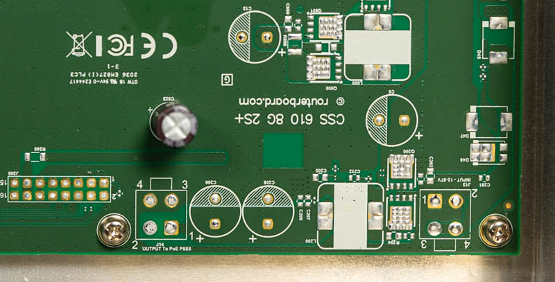
Implementation Plan
I will proceed with using the J14 header for power input:
- J14-4: Ground
- J14-2: Power input
The header pinholes measure 1.7mm and are spaced 5mm apart, so I need to determine a way to securely connect a new power jack without modifying the PCB. Possible solutions:
- Press-fit pins or sockets
- Screw terminal connectors
Mounting
Ears: https://makerworld.com/en/models/1190849-mikrotik-10-inch-mini-rack-ears-rmk-2-10-alternati#profileId-1202558
Hypervisor (Minix Z100)
The PC is powered with a 5.5x2.1mm barrel jack (12V-19V DC).
- No need to relocate plug
- Removed Wi-Fi
- Upgraded RAM
Beryl AX
- https://github.com/gl-inet/docs4.x/blob/master/docs/user_guide/gl-mt3000/index.md
- https://www.cnx-software.com/2023/01/08/gl-inet-gl-mt3000-wifi-6-router-review-specs-unboxing-teardown/
- Find board layout
- Antenna modification
- Connector standards
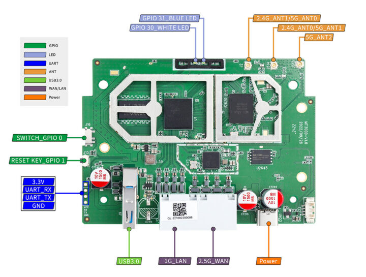
Internal antenna on back of case goes to J15