6 min to read
Keyboard Plan
This project uses readily available, open-source components as the starting point to bridge the the requisite skills to design and build a completely custom keyboard, starting from the the PCB design phase. The goal of this project is to build a premium, wireless, split spacebar keyboard powered by ZMK.
PCB and Firmware
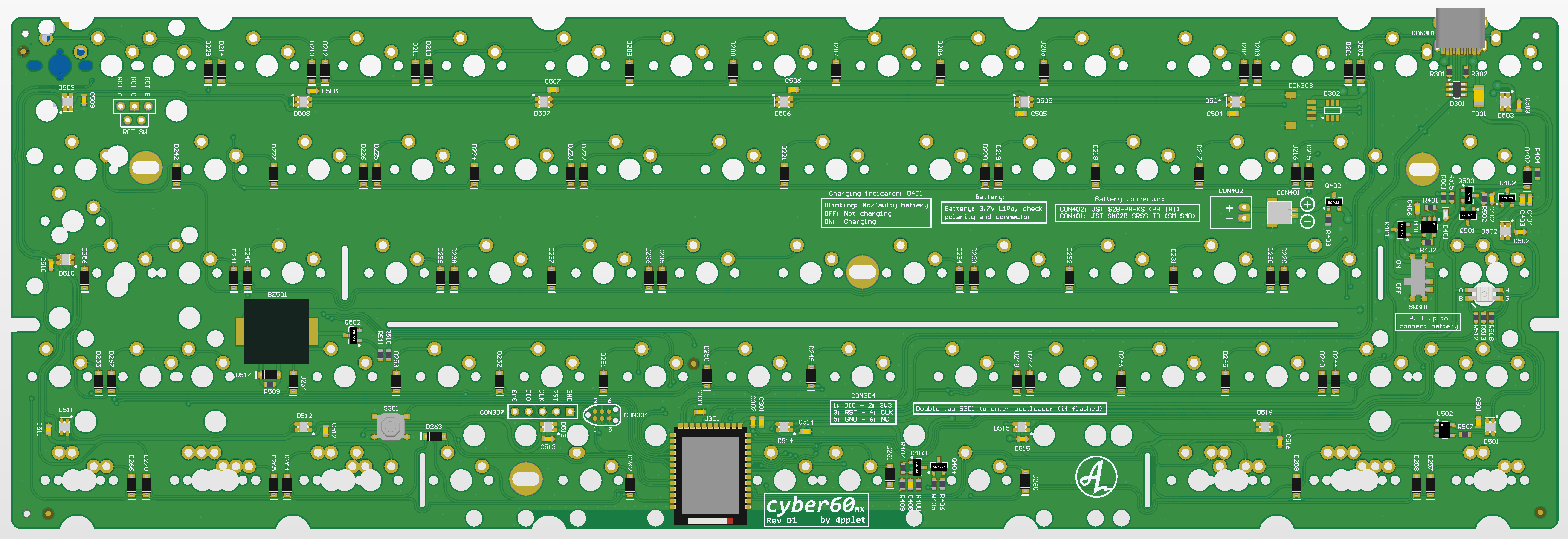
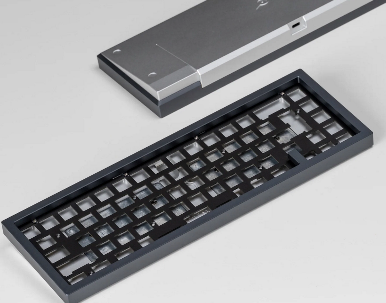
Cyber60 PCB
This project uses the Cyber60 board by 4pplet. The board features:
- Holyiot YJ-18010 MCU
- nRF52840 Bluetooth module
- Open source ZMK firmware
- 2.75U+1U+2.75U split spacebar support
- Unified USB C Daughterboard support
- Hotswap switches via Mill-max sockets
Layout
The following keyboard layout is generated from Keyboard Layout Editor and is useful for many tools which help automate keyboard design such as Plate & Case Builder.
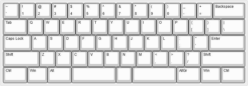
["~\n`","!\n1","@\n2","#\n3","$\n4","%\n5","^\n6","&\n7","*\n8","(\n9",")\n0","_\n-","+\n=",{w:2},"Backspace"],
[{w:1.5},"Tab","Q","W","E","R","T","Y","U","I","O","P","{\n[","}\n]",{w:1.5},"|\n\\"],
[{w:1.75},"Caps Lock","A","S","D","F","G","H","J","K","L",":\n;","\"\n'",{w:2.25},"Enter"],
[{w:2.25},"Shift","Z","X","C","V","B","N","M","<\n,",">\n.","?\n/",{w:2.75},"Shift"],
[{w:1.5},"Ctrl",{w:1.25},"Win",{w:1.5},"Alt",{a:7,w:2.75},"",{w:1},"",{a:7,w:2.75},"",{a:4,w:1.5},"AltGr",{w:1.25},"Win",{w:1.5},"Ctrl"]
ZMK Firmware
Documentation is availble here
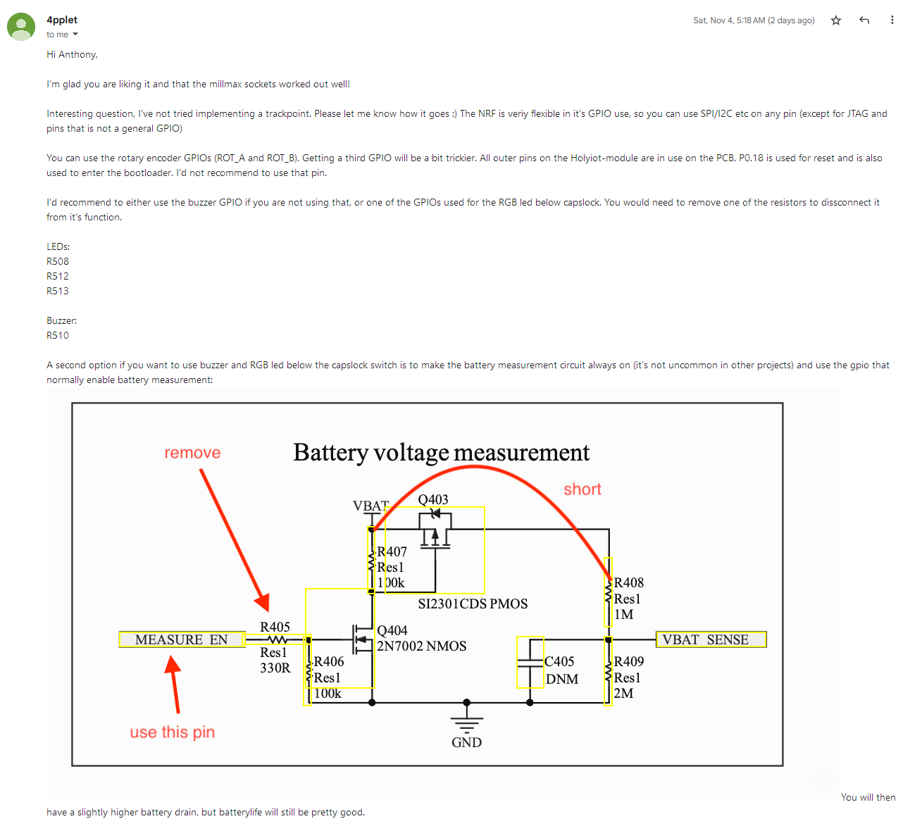
Pointing Device Support
Pointing devices are not currently not supported in the release version of ZMK, however, the feature branch from urob has an implementation pending PR.
While it is generally possible to integrate a pointing device with the MCU, there are not enough free accessible pins to do so. Three GPIO pins are needed. Since I will not be using a rotary encoder, ROT_A and ROT_B provide two pins. The third will need to be repurposed from another component. 4pplet recommends using the buzzer or caplock LED, however, modifications are necessary.
Instead, I will implement pointing mouse emulation via IJKL keys.
- Update
west.ymlto point to feature branch (Reference) - Mouse emulation is not currently supported in GUI keyboard editing tools, so has to be manually added to keymap file
- Draft ZMK documenation
- https://rfong.github.io/rflog/2021/10/26/r61-trackpoint-pt2/
- https://github.com/manna-harbour/crkbd/tree/master/trackpoint#driver-board
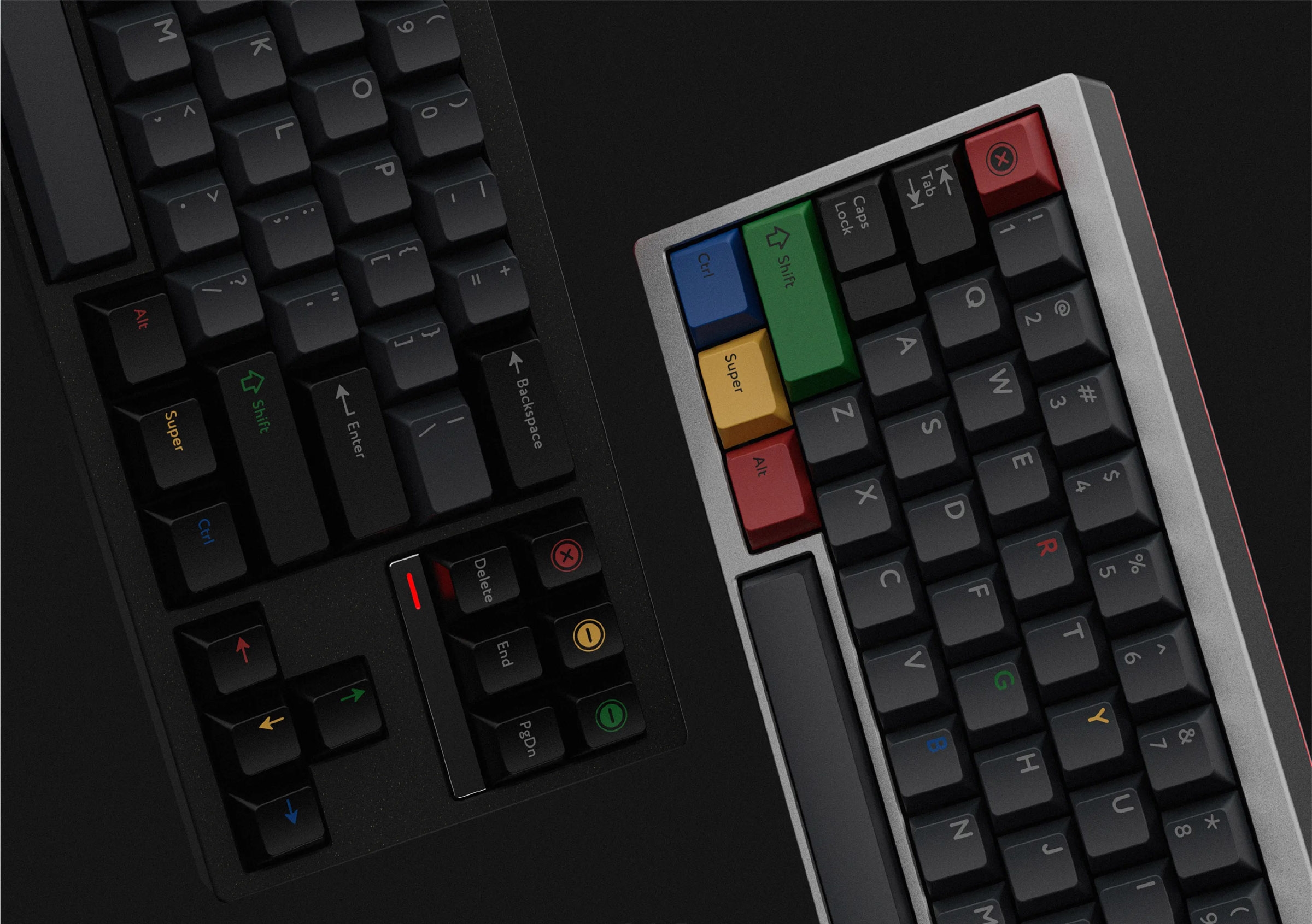
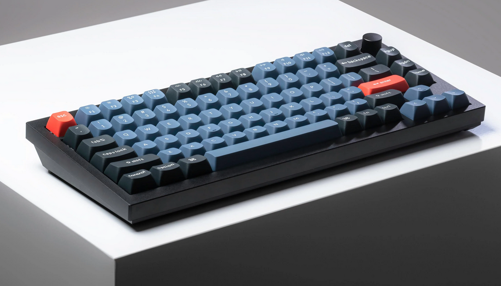
Inspiration
While gasket-mount case constructions are very popular right now, due to allowing flex in the keyboard, I am not convinced about the value added. My case is designed as a tray-mount. Construction of the case uses a sandwitch design which means that the overall vertical thickness of the case is made up of several layers. The main body of the case will be constructed using stacked leather. This is a technique used in the construction of handles for tools and knives. The process involves compressing leather and then shaping it. This technique is also found in shoemaking. The end result is comparable to wood.
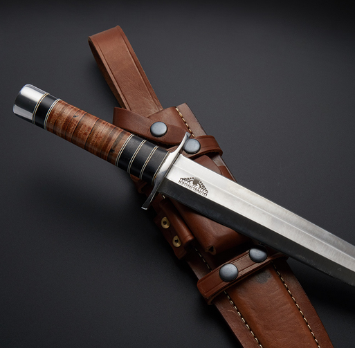
For the overall case design, I’m going for: thick bezels, hard eges, angular. Some references:
Keychron
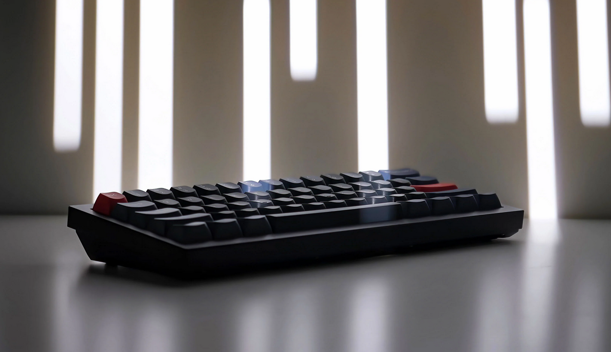
PBTfans Retro Dark Light keycaps
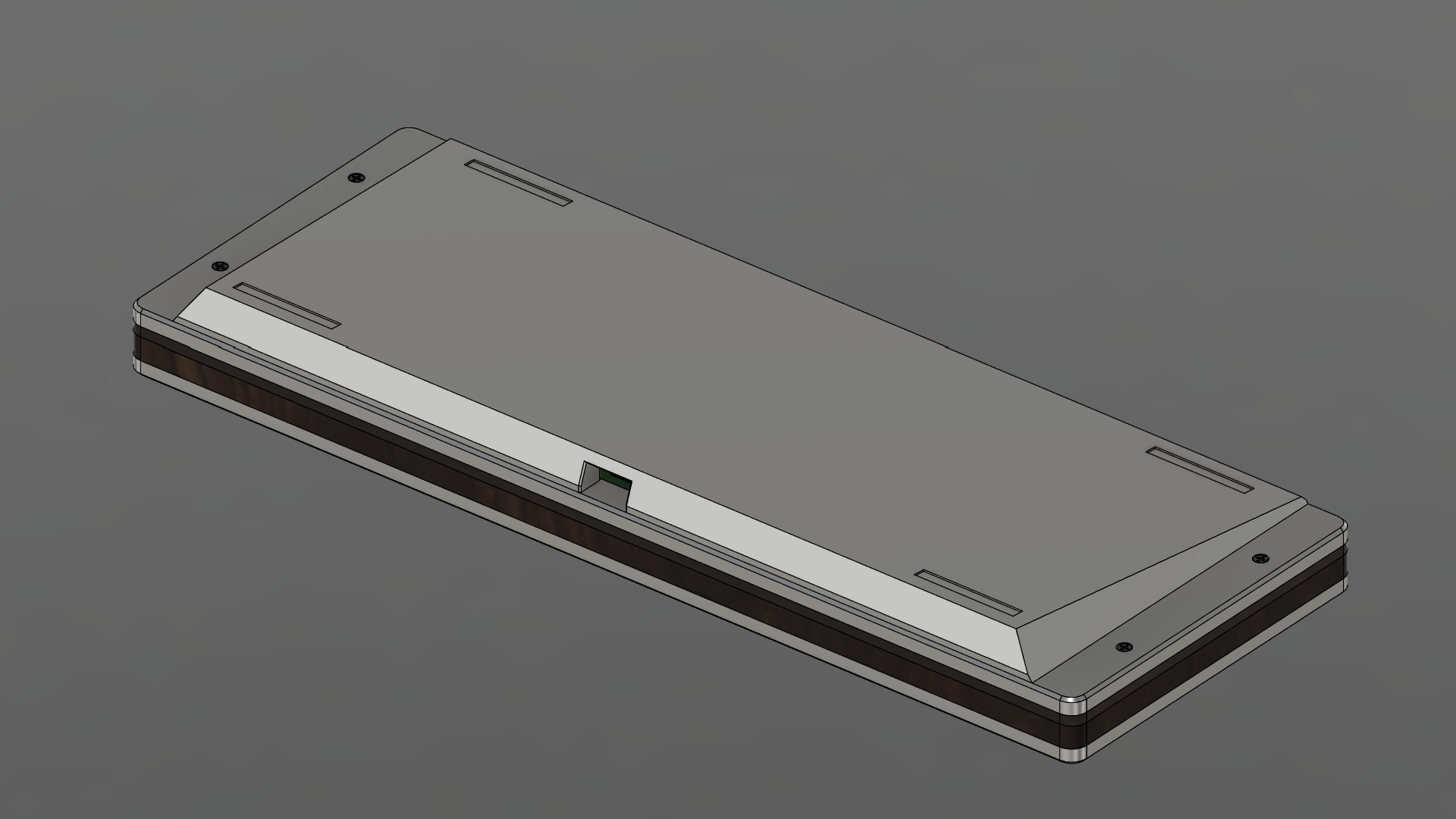
Design
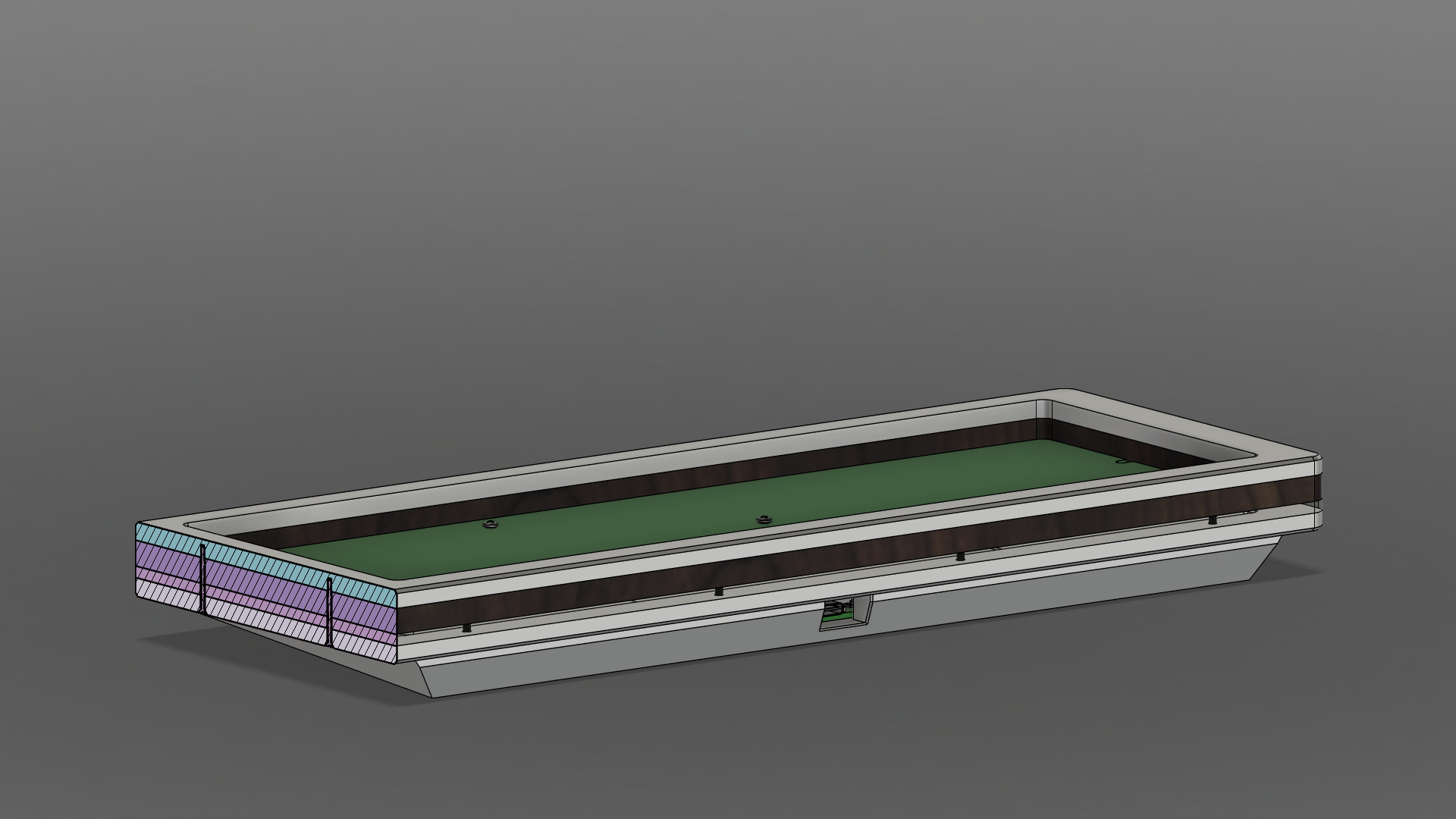
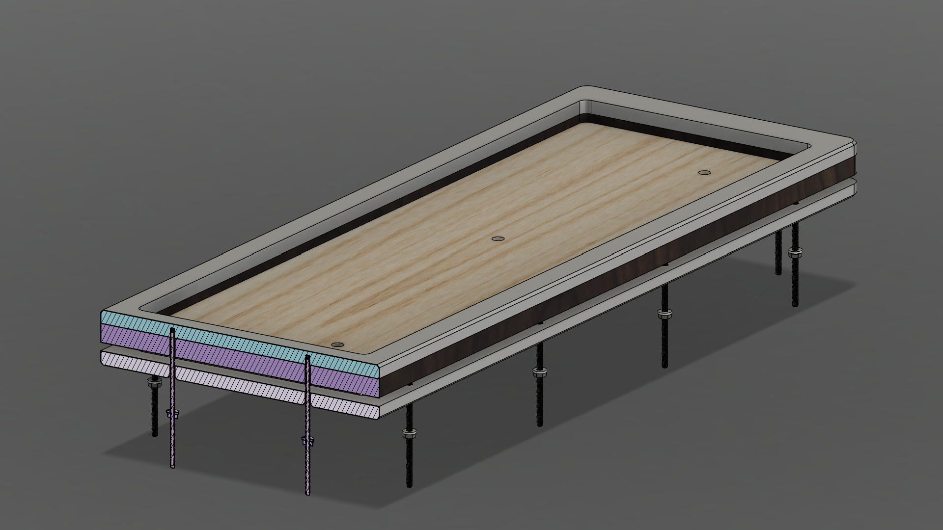
The body of the case consists of four layers:
| Layer | Thickness | Material |
|---|---|---|
| Top plate | 5mm | Metal |
| Body | 7mm | Leather |
| Transparent diffuser | 1/8” | Acrylic |
| Bottom plate | 5mm | Metal |
| Base (wedge) | 11mm (at thickest) | Metal |
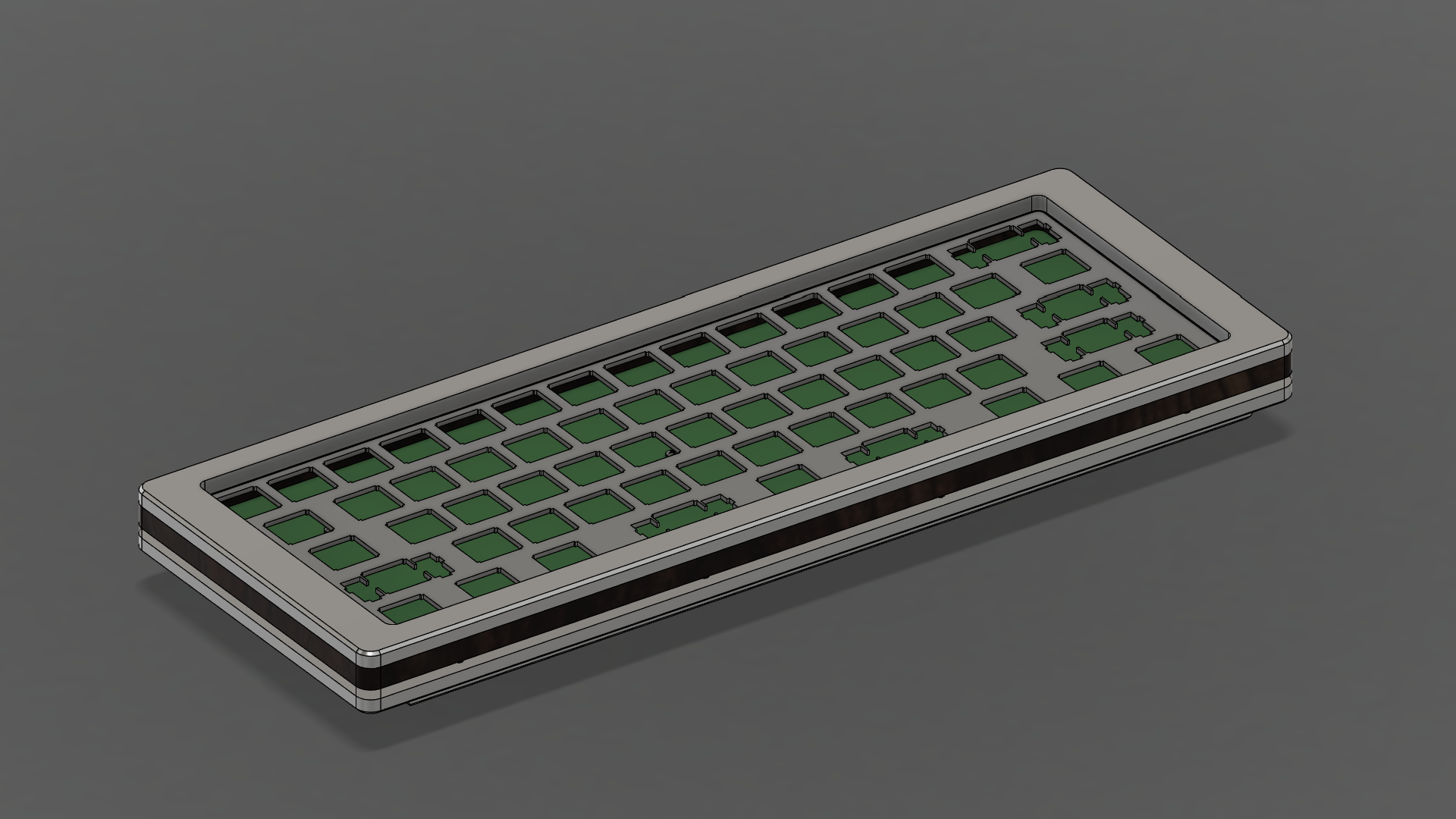
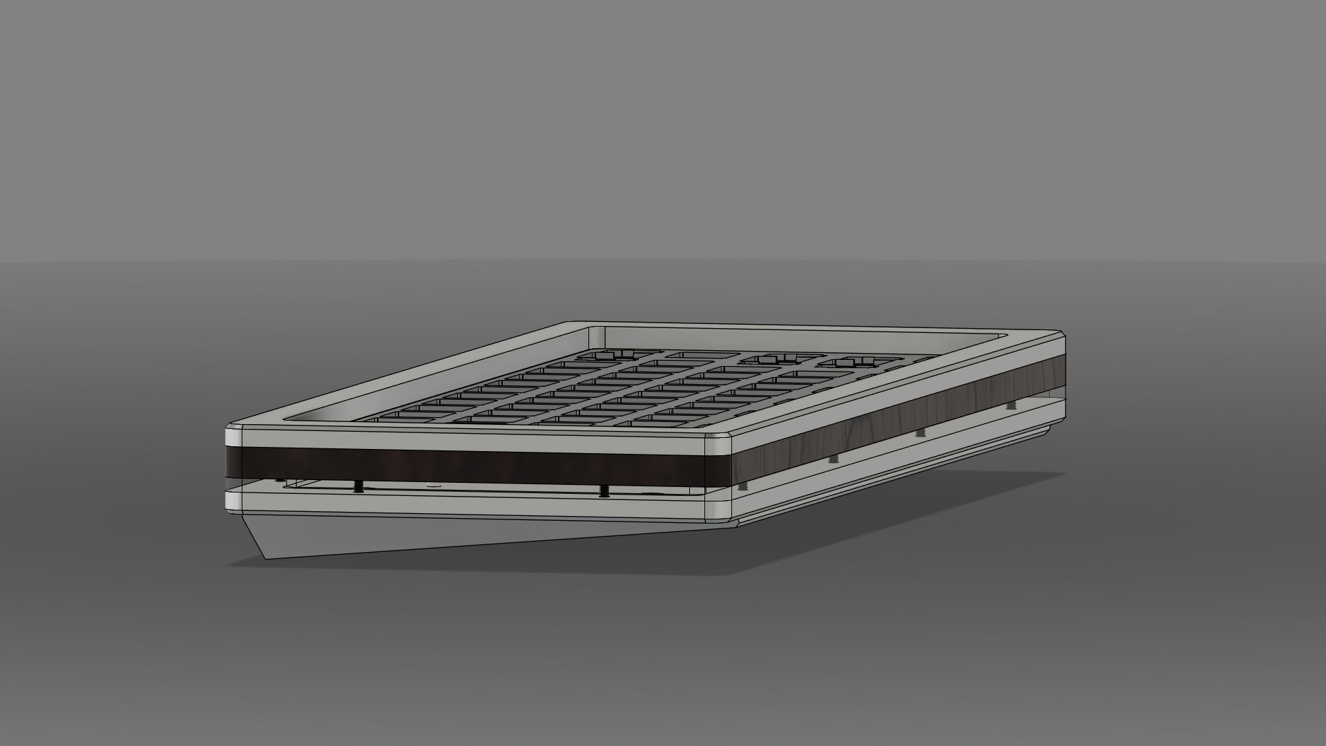
The most complicated piece is the base which provides the keyboard a 5-degree tilt.
Layers
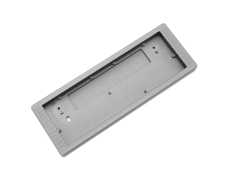
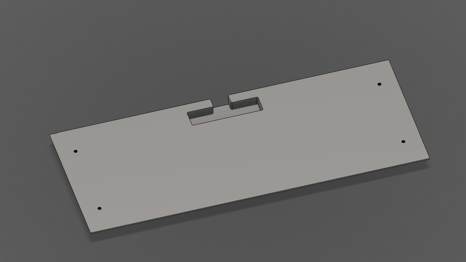
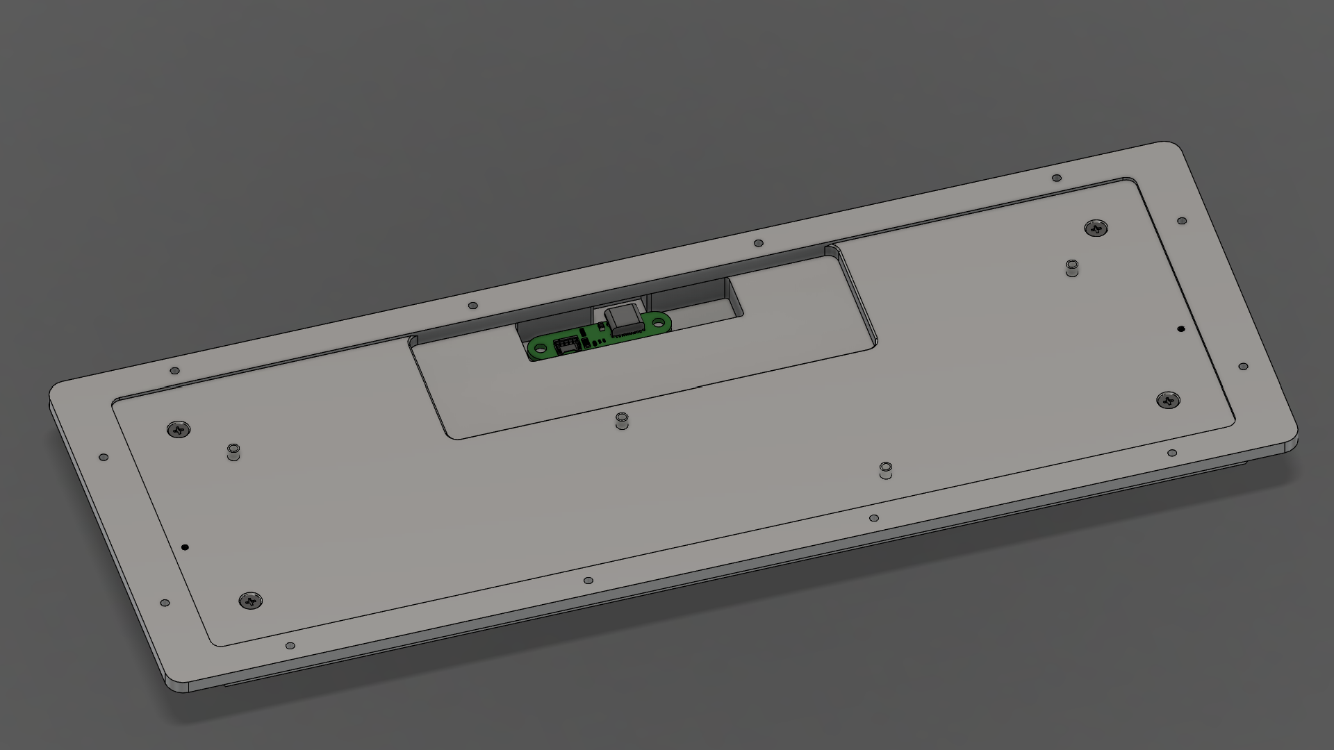
Bottom Plate
The bottom plate is machined from a single sheet of 1/4” material down to 5mm.
On the top side:
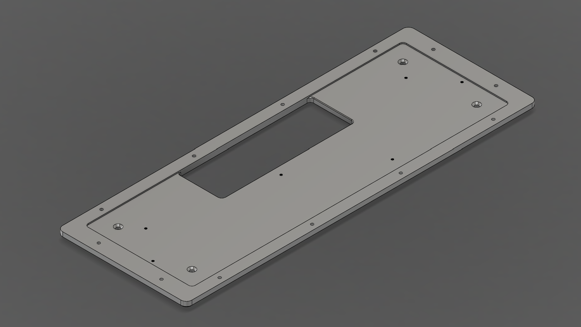
- PCB tray area recessed by 1mm
- 120mm x 40mm cutout for battery
- 4 countersuck holes for mounting the base
- M3
- Countersink diameter (6.30mm)
- Drill through
- 6 tapped holes for attaching PCB
- M2
- Drill through
On the bottom side:
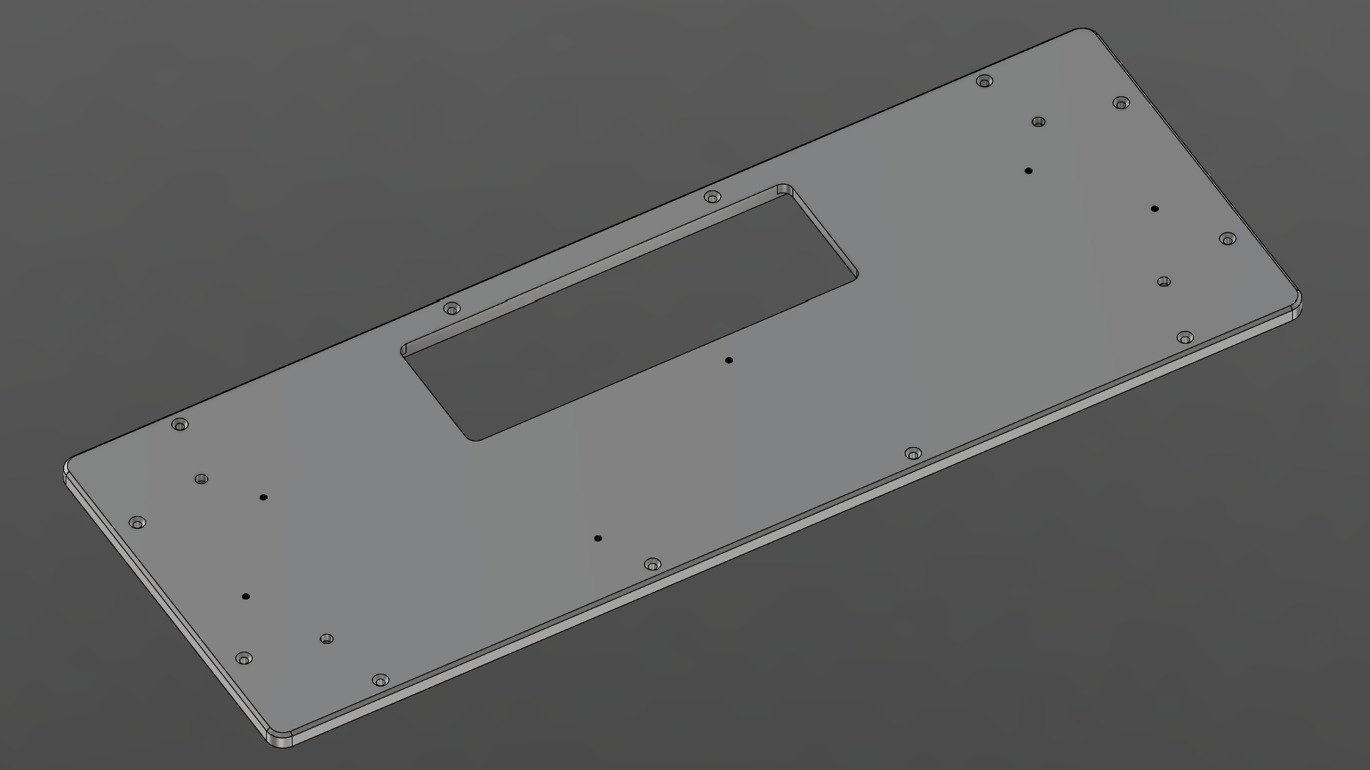
- 1mm chamfer around the outer perimeter
- 12 countersunk holes for the body assembly
- M2
- Countersink diameter (4.40mm)
- Drill through
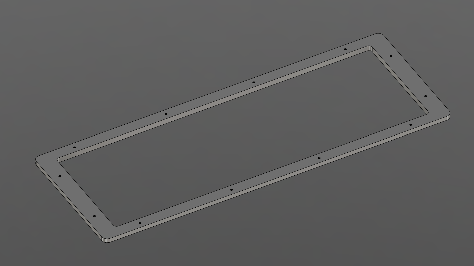
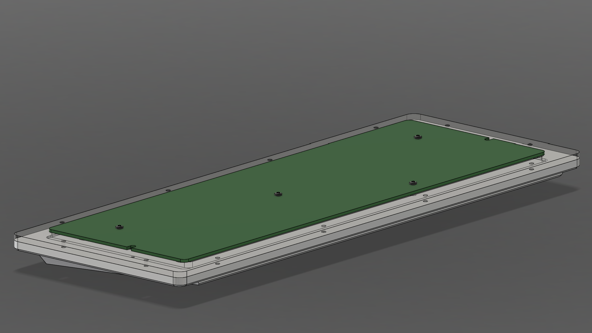
Mid Body
The body of the case consists of an acrylic layer (1/8”) and stacked leather. Construction of the stacked leather is covered (here).
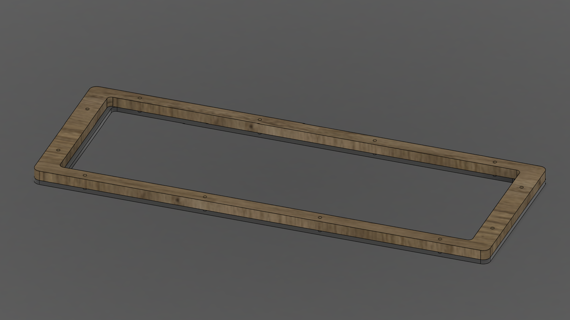
For the acrylic piece:
- 12 holes for the body assembly
- M2
- Clearance hole
- Drill through
Note the overhang lip on the shorter side: the PCB sits on this surface. In the middle, the PCB is held up by with spacers.
Top Plate
The top plate is machined from a single sheet of 1/4” material down to 5mm.
On the top side:
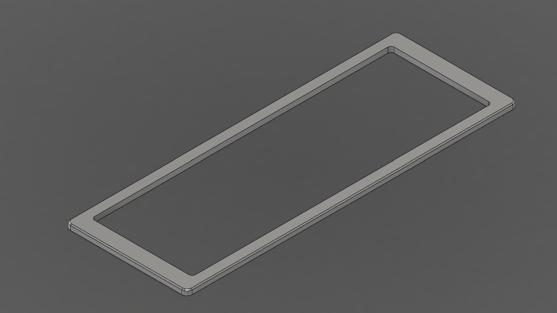
- 1mm chamfer around the outer perimeter
On the bottom side:
- 12 tapped holes for the body assembly
- M2
- Drilled 3mm (not visible from the top side)
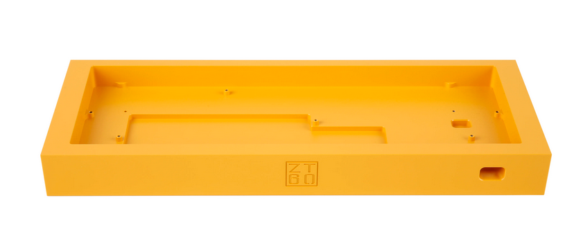
Wedge
The base is machined from a single sheet of 1/2” material.
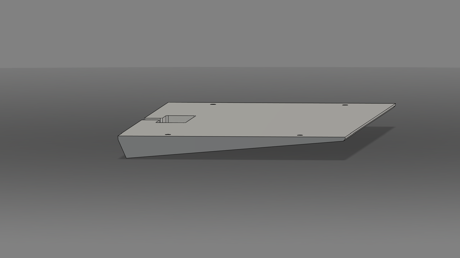
I have no idea how this is to be done, how complicated it is, or if it is feasible. The general shape is a 5-degree wedge. The additional geometries are visual.
On the top side:
- 15mm x 60mm cutout for the USB C daughterboard, at a depth of 8mm
- 4 tapped holes for mounting to the bottom plate
- M3
- Drilled 2.5mm
On the bottom side:
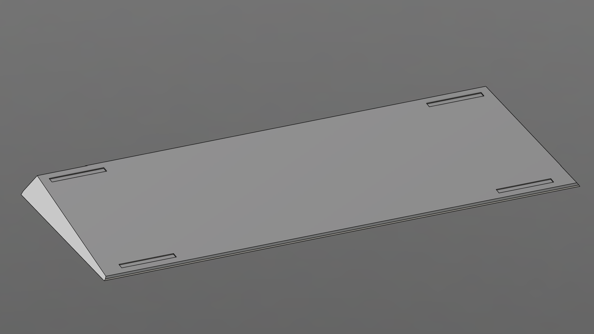
- Slots for feet
Assembly
Construction
Leather Stack
General idea: https://www.instructables.com/Stacked-Leather-Knife-Handle/
The bottom plate and cutout of the PCB tray forms the mold in which to shape the leather. The cutout ensures that inside face is formed precisely.
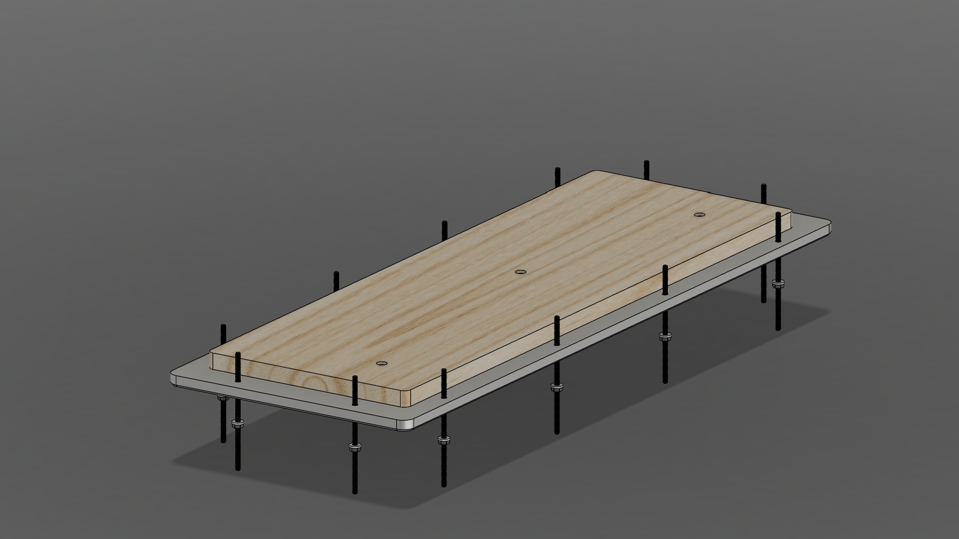
Wet leather pieces in the shape of the case are then fit between the top and bottom plate and compressed using threaded rods, washers and bolts. It is important to ensure that the leather is uniformly compressed.
Since the interior edge is constrained, the compressed leather will expand towards the outer side. When dry, the excess leather can be cut/sanded off indexed by the top and bottom plate. This should produce a perfectly flush finish.
The leather stack should then be disassembled, glued back together, and polished.
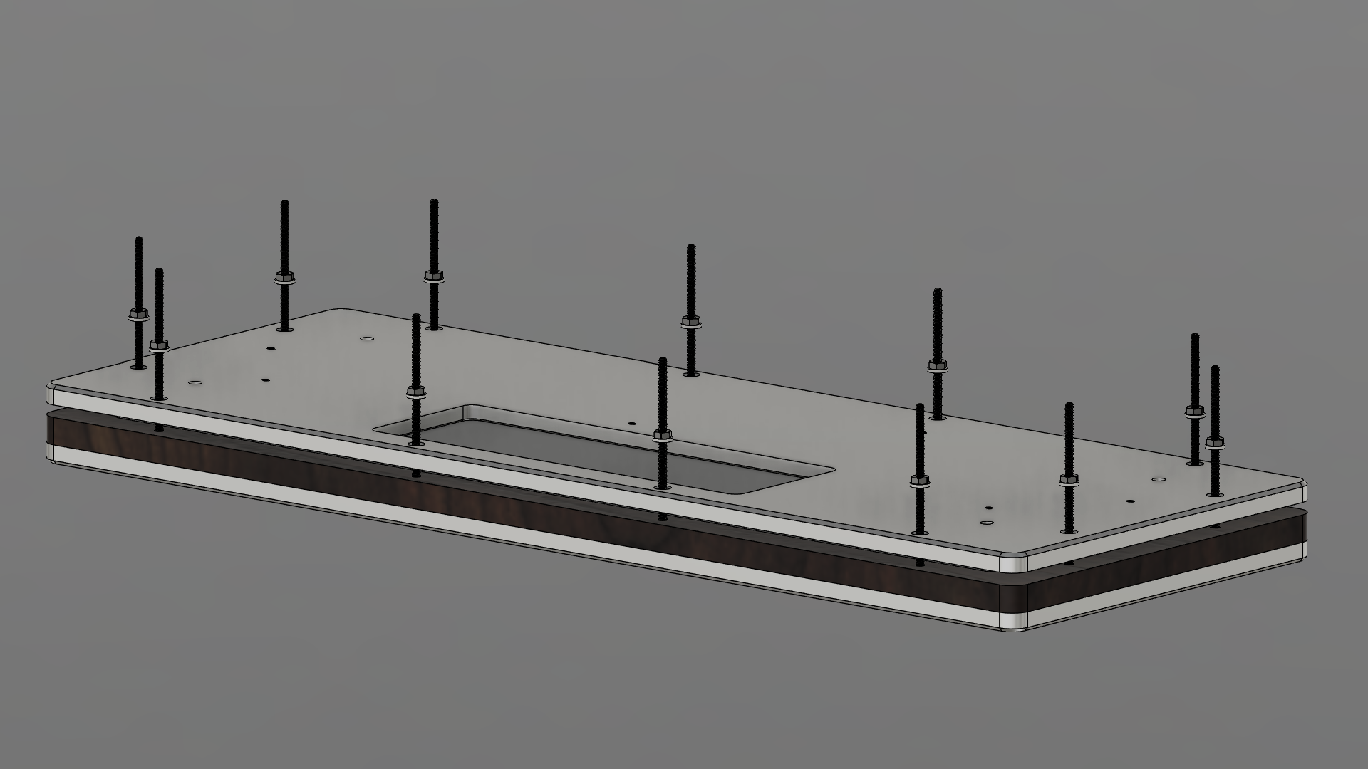
This is how the press assembly works.
Bill Of Materials
etc etc scrap notes
For the metal and acrylic, each plate requires minimally 13”x5” of material.
- Multipurpose 6061 Aluminum Sheet
- 6”x48”x1/4” ($60.18)
- https://www.mcmaster.com/9246K424
- For top/bottom plates
- 6”x12”x5/8” ($45.78)
- https://www.mcmaster.com/9246K524
- For wedge
- 6”x48”x1/4” ($60.18)
- Clear Scratch- and UV-Resistant Cast Acrylic ($17.70)
- 12”x24”x1/8”
- https://www.mcmaster.com/8560K257
- For diffuser
- 12”x24”x1/8”
-
butt ton of screws, washers, etc
- USB C to JST connector
- https://cannonkeys.com/products/unified-c4-daughterboard
- Molex to JST cable
- https://cannonkeys.com/products/molex-and-jst-cables?variant=41098401972335”
- https://www.youtube.com/watch?v=DJULiA1aTtM&list=PLrZ2zKOtC_-C4rWfapgngoe9o2-ng8ZBr&index=28